Cashco HP Manuel d'utilisateur
Naviguer en ligne ou télécharger Manuel d'utilisateur pour Capteurs Cashco HP. Cashco HP User Manual Manuel d'utilisatio
- Page / 8
- Table des matières
- MARQUE LIVRES
Résumé du contenu
INSTALLATION, OPERATION & MAINTENANCE MANUAL (IOM) IOM-HP 12-13MODEL HPPRESSURE RE DUC ING REGULATORSECTION II. DESCRIPTION AND SC
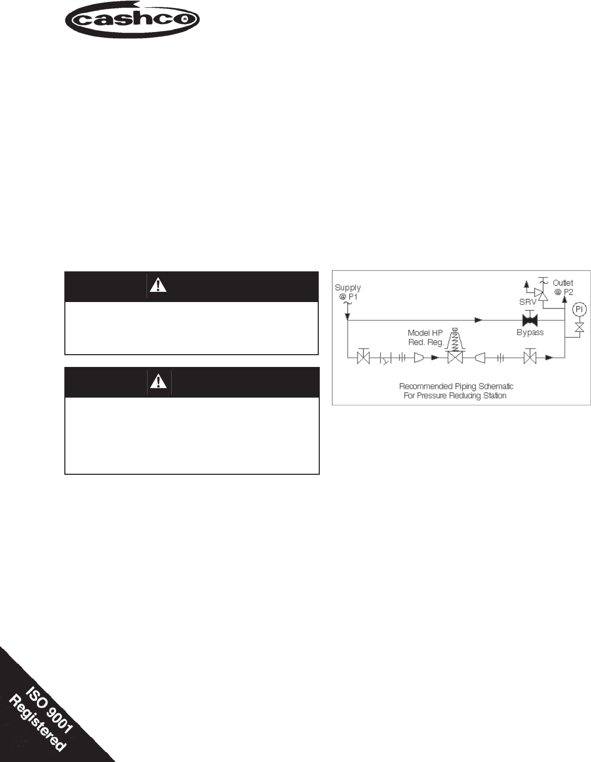
IOM-HP2SECTION III* NOTE: Systems sequencing operations at startup, normal operation, failure mode(s), and shutdown must as-sure that the pressure (
IOM-HP3SECTION VIVI. MAINTENANCE2. Relax range spring (14) by turning adjusting screw (6) CCW until removed from spring cham ber (2).3. Draw or emb
IOM-HP4E. Special Instructions for Diaphragm Re place ment:1. For the Option -1+6 Differential Con struc tion, re as -sem ble the diaphragm sub as s
IOM-HP5SECTION VIIVII. TROUBLE SHOOTING GUIDE1. Erratic operation; chattering.Possible Causes RemediesA. Oversized regulator; inadequate rangeabil
IOM-HP6SECTION VIII5. Sluggish operation.Possible Causes RemediesA. Plugged spring chamber vent. A. Clean vent opening.B. Plugged piston balance po
IOM-HP7NOTES
FIGURE 1Model HP – Metal Seat Item Repair Parts No. Description Kit A Kit B 1 Body 2 Spring Chamber 3 Pressure Plate 4 Spring Button 5 Body Cap
Plus de documents pour Capteurs Cashco HP

Produits connexes et manuels pour Capteurs Cashco HP
 (8 pages)
 (20 pages)
(16 pages)
(16 pages)
(16 pages)
(12 pages)
(12 pages)
(20 pages)
(20 pages)
(20 pages)
(16 pages)
(16 pages)
(16 pages)
(12 pages)
(12 pages)
(20 pages)
 (8 pages)
(9 pages)
(8 pages)
(8 pages)
(9 pages)
Relacionado con productos y manuales para Reproductores de dvd Yamaha NS-P110
 (60 paginas)
 (4 paginas)
© 2020, manymanuals.fr. Tous droits réservés | 0.161 s |
 Manymanuals.com
 Manymanuals.de
 Manymanuals.fr
 Manymanuals.it
 Manymanuals.pl
 Manymanuals.cz
 Manymanuals.es
 Manymanuals-pt.com
Commentaires sur ces manuels